Before you install your new PICTIM ignition system on your engine, I highly recommend you do a simple bench test with it and all the components. This way you will be more familiar with it and see how it actually works. Otherwise, once installed on the engine, issues sometimes show up such as bad connections and open grounds - making it much more difficult to diagnose the system as a whole.
Once you get it working on the bench, proceed by installing just ONE component at a time on the engine, and re-test. If it still works, install the next component and re-test. Repeat until the entire system is installed. If it quits working after you installed a particular component, then you know you have a connection problem with that component.
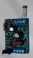
See the photos below for how I bench test the PICTIM and the Power Keg coil.
- The two black coil wires are connected to Coil + and Coil - on the PICTIM (the Power Keg coil is NOT polarized unlike the Universal ATV or other "3 wire" coils)
- The white leads will simulate the spark plug, so position them so they are 1/16" to 1/8" apart. No more, no less or you can damage the coil. If you have the red universal ATV coil; simply position the end of the spark plug wire 1/16" to 1/8" from the coil frame and the spark will jump here.
- I connect a 9v smoke alarm battery to Batt + and Batt- on the board.
- Using a bent paper clip, quickly touch and release positions 1 and 3 on the switch connection block. This simulates a "points" system. Each time you make a connection you should see the LED light up and a spark jump across the white wires of the coil.
(click photos to enlarge)
If this is successful, and if your setup will be using the Hall/Magnet switch, then resume testing:
- Disconnect Batt +.
- Hook up the Hall sensor directly to the switch block following the PICTIM wiring diagram PDF, or alternatively use steps 3-7:
- Gently bend the middle lead of the Hall sensor away from the other two.
- Wrap a small strip of tape around the two outer leads as close to the head as possible, leaving half of the bottom of the leads exposed.
- With the Hall bevel facing up and leads towards you, bend the middle lead 2 to the left so it is now "third" from the right. Lead 1 should still be straight and will now be "second". Lead 3 will also be straight and "first" from the right.
- The tape serves as an insulator in case the leads touch. Verify that the bent middle lead is not touching and other leads.
- Insert the Hall sensor into the terminal block, face up, into block positions 1,2,and 3 as shown in the photo below:
 |
| (click to enlarge) |
8. Reconnect Batt +.
Wave your magnet's south pole across the face of the Hall sensor. At each pass, the LED should light and a spark should jump between the coil's white leads.
Final Test:
As a final test before you install anything on your engine, connect the spark plug to the coil. In the case of the Power Keg, simply connect one white wire to the top of the spark plug, and the other white to the bottom threads.
If you are using the red universal ATV coil, simply connect the coil spark plug wire to the top of the spark plug, and connect the frame of the coil to the spark plug threads.
When you test the PICTIM now, you should see the spark in the spark plug gap. If not, check connections, or you may have a faulty spark plug.
-----------------------------------------------------------------------------------------------------------------------
If these test pass, you are ready to install the system on your engine. I would install the components in the following order, testing that everything still works IN BETWEEN each component install:
- Spark Plug
- Points or Hall/Magnet
- Make sure the Hall sensor install, and it's wires, are well insulated from the engine frame. Some of our instructions recommend you also ground the module (from the "Gnd" on the board terminal block) to the engine frame. This is to provide a path for the coil's high voltage to ground in case the Hall sensor or wiring is too close to the engine. If you're getting good spark after installing the spark plug, hold off on this step. However, if your have a problem with Hall sensors blowing out, try this ground.
- PICTIM module
- Battery
If these steps are followed, you are much more likely to have a trouble-free install. If you have any trouble along the way and just can't figure it out, feel free to e-mail allen@outpostenterprises.com with photos and a detailed description of the problem, and I will do my best to assist.
Good luck!


