Before you install your new TIM6 ignition system on your engine, I highly recommend you do a simple bench test with it and all the components. This way you will be more familiar with it and see how it actually works. Otherwise, once installed on the engine, issues sometimes show up such as bad connections and open grounds - making it much more difficult to diagnose the system as a whole.
Once you get it working on the bench, proceed by installing just ONE component at a time on the engine, and re-test. If it still works, install the next component and re-test. Repeat until the entire system is installed. If it quits working after you installed a particular component, then you know you have a connection problem with that component.
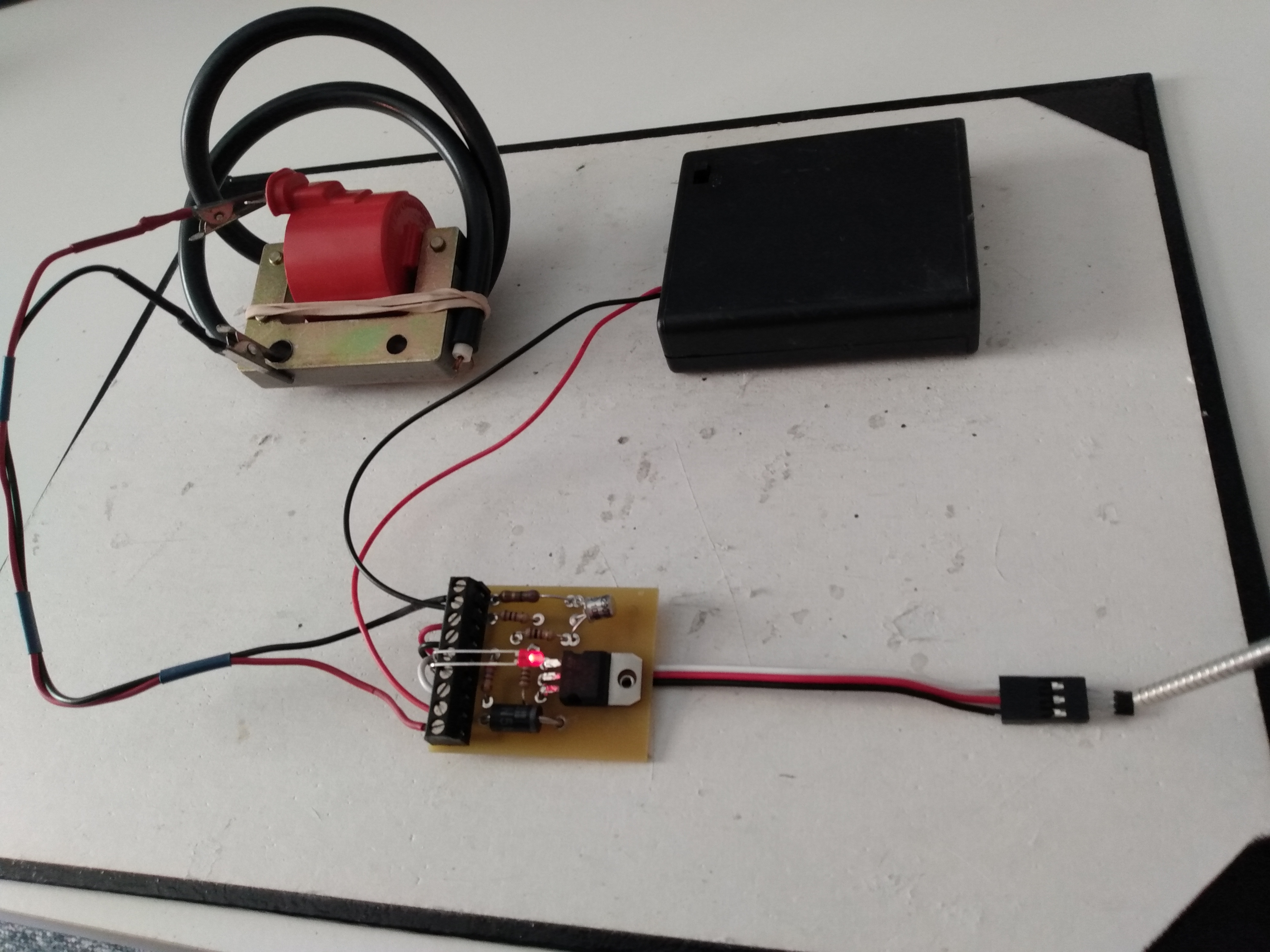
See the photos below for how I bench test the TIM6 with the ATV coil.
- The tab on the coil connects to "Coil +" and the coil frame is connected to "Coil -" on the TIM6 module.
- Cut the end of the coil's spark plug cable so that about 1/8" of the copper wire is exposed. Secure the spark plug wire to the coil frame so that the exposed wire is 1/16" to 1/8" from the coil frame. No more, no less or you can damage the coil. The spark will jump here.
- Connect your 6v battery to "6 volt+" and "6 volt -" on the module.
- Using a bent paper clip, quickly touch and release the "points" terminals on the connection block several times. This simulates a "points" system. Each time you make a connection you should see the LED light up, and when you release a spark will jump across the gap of the spark plug wire and the coil frame.
(Click photo to enlarge)
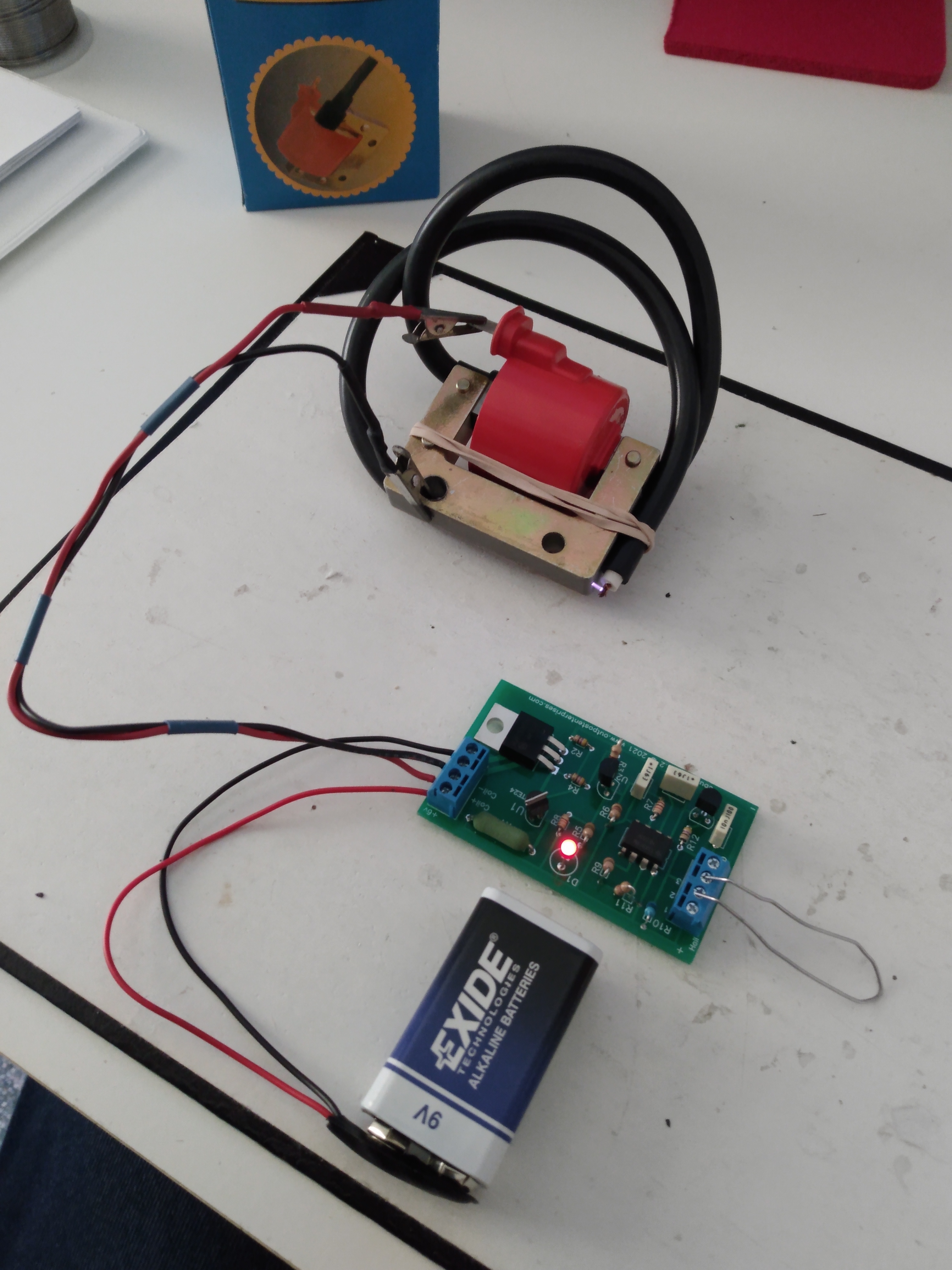
If this is successful, and if your setup will be using the Hall/Magnet switch, then resume testing:
- Switch off power, or disconnect "6 volt +" on the module
- Hook up the Hall sensor to the switch block following the TIM6 Instructions, or as shown in the photo below using our Hall wire.
- Reconnect power.
Wave your magnet's south pole across the face of the Hall sensor. At each pass, the LED should light and sparks should jump between the coil spark plug wire and frame.
(click photo to enlarge)
Final Test:
As a final test before you install anything on your engine, connect the spark plug to the coil. In the case of the ATV coil, connect the spark plug wire to the top of the spark plug, and position the plug threads so they touch the coil frame. A rubber band may be helpful to hold it in place.
When you test now, you should see the spark in the spark plug gap. If not, check connections, or you may have a faulty spark plug.
-----------------------------------------------------------------------------------------------------------------------
If these test pass, you are ready to install the system on your engine. I would install the components in the following order, testing that everything still works IN BETWEEN each component install:
- Spark Plug
- Points or Hall/Magnet
- Make sure the Hall sensor install, and it's wires, are well insulated from the engine frame. Some of our instructions recommend you also ground the module (from the "Gnd" on the board terminal block) to the engine frame. This is to provide a path for the coil's high voltage to ground in case the Hall sensor or wiring is too close to the engine. If you're getting good spark after installing the spark plug, hold off on this step. However, if your have a problem with Hall sensors blowing out, try this ground.
- TIM6 module
- Battery
If these steps are followed, you are much more likely to have a trouble-free install. If you have any trouble along the way and just can't figure it out, feel free to e-mail allen@outpostenterprises.com with photos and a detailed description of the problem, and I will do my best to assist.
Good luck!