Here's an e-mail I received from Don Holloway on Dec 27, 2011:
----------------------
Hi
I purchased plans for the precision mini drill press a while back and want to start to build soon.
The only thing that I don't see is the OD for the quill feed shaft gear.
Do you know what the OD of the gear should be?
Thanks and the best to you folks in the new year.
----------------------
My reply:
Don,
Good question. Nobody has asked me that before, and I did not realize it was missing. Unfortunately, Dad passed away over two years ago so I can't ask him, and his prototype does not have this gear exposed for me to measure it.
Would the pitch and angle of the gear teeth determine the diameter? I'm not a machinist, so maybe I'm all wet in that theory.
I will post your question on our user forum - perhaps some other builders will be able to assist. If not, I guess hold off on this part as long as possible, then perhaps the diameter can be surmised by the distance from it's shaft and the position of the quill - ???
Allen
--------------------
If anyone can help answer this more definitively, it would be appreciated!
Thx...
Tuesday, December 27, 2011
Wednesday, December 21, 2011
Siôn Silyn Robert's Cannon
Here's an e-mail I received from Siôn on Dec 21, 2011:
--------------------------------------------------
Hi Allen,
I think that I can only claim ‘inspired by’ for this and I confess that it is not very well made. I do not have much/any spare time. As you can see the bore size is relatively small so that it will be a bit safer if it is ever fired. The first cannon that I made many years ago was about half the size of this and has been fired a number of times. Even at that size it is potentially dangerous device, so this one needs to be treated with respect. The carriage is walnut and the wheels are plum wood from our garden, for sentimental reasons.
I will try to find time to make a better one.
All the best and have a relaxing holiday,
Siôn
-------------------------------------------
Thanks Siôn - looks OK to me!

Monday, November 21, 2011
Ralph Ervolino's Farmboy projects
Here is the url for the large Farmboy:
http://www.youtube.com/watch?v=bhXJgAag1uM
Here is the one for the small one:
http://www.youtube.com/watch?v=sEi_rz20ljI
http://www.youtube.com/watch?v=bhXJgAag1uM
Here is the one for the small one:
http://www.youtube.com/watch?v=sEi_rz20ljI
Saturday, November 19, 2011
Ken Morris's Mini-Drill motor
Ken sent me this e-mail on Nov 19th:
--------------------------------------------
"I used an electric motor from a Beam central vac powerbrush. To control the speed I used a router speed control. Motor cost is about $30.00. Mounting is no problem but the speed control is necessary. Ken"
I asked for verification of the drill used on - Micro Drill or Mini Drill. He replied:
"HI Allen. RE: drill press motor. The motor fits the mini drill press and is an exact fit. Brackets can be made easily and the shaft is .250. It is a 120 v motor and once again this motor is fitted into the beater head of the Beam central vac. I use a router speed control to monitor the speed. I have more pictures. Thanks, Ken"

Tuesday, November 8, 2011
More photos of Terry Mayhugh's V-Four
After two years of work it is done and running. A Youtube link shows my second successful run:
I machined the intake and exhaust manifolds from bar stock and finished them to look like cast parts. I also made my own distributor cap. - Terry


Tuesday, September 27, 2011
Jerry McKenzie's Miser
Allen,
Finished up my Miser engine and it runs great. Attached a couple of pic's, as you will see I made a couple of changes to flywheel and support column since I do not have a rotary table for mill yet. Think it looks OK anyway.
Ordered plans for a Beamer Engine, so that will keep me busy for awhile.
Cheers,
Jerry

Sunday, September 11, 2011
Dana Hall's V-Twin
Here's an e-mail I received from Dana on Sep 11, 2011. He did a superb job indeed!
--------------------------------------------------------------------------------
Hi Allen...
Dana Hall here from central Florida...
At the start of this year I purchased Jerry's "V Twin" plans, and just
finished building the engine today... Just about 8 months for me to make this...
Enclosed are 3 images of the engine I thought you might like to see...
Looks like the "Bill" engine is next...


Thursday, April 21, 2011
Steve Sedgall's Farmboy (not quite finished yet)
Here's an e-mail and photos I received from Steve on April 20, 2011
-------------------------------------------------------------------------------------------------
Hi,
I thought I would share with 2 pictures of my Farm Boy which I have just finished. It has run for about 10 minutes and now it s going to stripped and painted. I am very pleased with the results and it was a joy to work with such detailed and accurate drawings. I am looking forward to deciding on my next Jerry Howell project.
Kind Regards
Steve Sedgall
UK

 -------------------------------
steve,
looks real nice,i am in the process of putting mine together. did you use the spark saver on yours?what are you using for fuel?i assume that on the crank bushing that the flange goes on the inside correct?thanks for the pics i will post mine when done. i have also build jerrys powerhouse and it was easy to build and runs real good. thanks
toolmaker
--------------------------------
Here's another e-mail from Steve:
--------------------------------------------------------------
Hi Allen,
Here is a link to a video of the first time my engine ran.
http://www.youtube.com/watch?v=YV9yEF8nq2g
Steve Sedgall
Toolmaker ER
-------------------------------------------------------------------------------------------------
Hi,
I thought I would share with 2 pictures of my Farm Boy which I have just finished. It has run for about 10 minutes and now it s going to stripped and painted. I am very pleased with the results and it was a joy to work with such detailed and accurate drawings. I am looking forward to deciding on my next Jerry Howell project.
Kind Regards
Steve Sedgall
UK


steve,
looks real nice,i am in the process of putting mine together. did you use the spark saver on yours?what are you using for fuel?i assume that on the crank bushing that the flange goes on the inside correct?thanks for the pics i will post mine when done. i have also build jerrys powerhouse and it was easy to build and runs real good. thanks
toolmaker
--------------------------------
Here's another e-mail from Steve:
--------------------------------------------------------------
Hi Allen,
Here is a link to a video of the first time my engine ran.
http://www.youtube.com/watch?v=YV9yEF8nq2g
Steve Sedgall
Toolmaker ER
Friday, March 25, 2011
Alan Whiter's "Vickie"
Here's an e-mail I received from Alan Whiter on March 25, 2011:
-----------------------------------------------
HI
Have just finished the Vickie Engine but with a small burner flame it would not drive the fan so I added a flue which added the extra heat required, it now runs extremely well and is much admired by all.
I have also ordered the super stirling fan for my next project and hope to eventially construct the Farm boy and Howell V twin engines.
The drawings are exceptional and construction notes excellent.
Regards
Alan Whiter

Friday, March 11, 2011
V-4 Distributor Miter Gear Source
DOES ANYBODY HAVE A SUPPLIER FOR THE 15 TOOTH 48 PITCH MITER GEAR SET FOR THE V-4. THE SUPPLIER WAS SUPPOSED TO BE SMALL PARTS.COM. AS PER THE LATE MR.HOWELL, HOWEVER THEY NO LONGER HANDLE THEM. I CAN'T SEEM TO FIND A SUPPLIER, CAN ANYBODY CLUE ME IN ?
REGARDS TURTLEHEAD
----------------------------------------
Here's what Jerry recommended to me via email when I asked him that question.
"The Stock Drive gears Part Number A 1B 4-Y48015 will work. I don't
know what the cost is.
wmberg.com has 72 pitch stainless gears that are more precision,
but they cost $65.00 plus $15.00 shipping. Part Number M72N-7S
I will probably get these a little later on when I make a 1-1/4" diameter
distributor for the V-Fout because they are far more precision than
the Small Parts or the SDP gears.
Regards,
Jerry Howell"
As above he suggests "Stock Drive Products" as a source of the original gears. You should be able to find your local distributor for them from their website.
The 72 pitch gears Jerry mentions are larger in diameter than the originals and are not a direct replacement.
Since I was making the V8, my distributor had to be designed larger in diameter (I chose 1-1/2") else the spark towers would be too close together so I re-designed the whole distributor with a larger tower diameter to accommodate them. Very expensive though, but they provide almost no backlash in the rotor which I guess should result in more accurate timing.
Sage
Friday, February 11, 2011
New Intake Design by Dave Sage
On my V8 version of Jerry's V4 I had trouble with a water leak under the temporary intake manifold I constructed. I decided to split the two functions. As you'll see in the pictures I have two water inlets in the V8 so I made a long block to carry the water and added four 2-56 screws around each water inlet to pull the block down onto the O-rings in the block. This makes it independant of the intake. The intake can be removed (since it is still experimental in my case) without having to get involved with the water.
My new intake is made from bent stainless tubing - the same tubing and bender was used as the headers and the 90deg bends just fit. The whole assembly is silver soldered together. The carburetor is screwed onto a plate which is then screwed onto the stainless intake chamber. This will allow me to change carburetors if required by fabricating a new plate to suit the carb to be installed.
I can highly recommend separating the water funtion from the intake manifold function. This will also keep the intake charge cool instead of it being heated by the water.
Tuesday, January 11, 2011
Terry Mayhugh's fabricated exhaust manifolds
Here are some pictures of the exhaust manifolds that I just completed for my V-4. I machined this from billet and then glass-beaded them to give them a 'cast' look. In another thread I showed how I created the intake manifolds from two identical halves, but I felt the exhaust manifolds needed to be machined from a single workpiece due to the extreme temperatures to which they would be exposed. I started with a suitably sized rectangular workpiece and then it it I drilled the long exhaust runner. I then drilled the two short runners as far as I could before the angle into the block flange became too acute. I then pressed plugs into the short runners to a depth such that half of the diameter of the long runner would be closed off. I also pressed pins into these plugs where the wall the manifold itself would eventually be as a safety measure to help secure the plug. Plugs and pins were also secured with high temperature bearing retainer. I then re-drilled the long runner to clear out the remnants of the two short runner plugs. I used a spherical D-bit to blend the long runner with the far-end short runner. I then machined the the top of the manifold and then flipped it over to mill the backside. This is where things get tricky. Finish machining the backside will cause the part to drop free before the machining is completed and so before starting the backside machining I epoxied the already top-side machined part to a plate that was secured to the workpiece with a number of screws. This kept the part stable after it was cut free from the workpiece and allowed me to do all the back side machining. After both sides were completed I heated the epoxy up to 200F and it released easily from the workpiece. Essentially no clean-up was needed and so I needed only to drill out the short runners from the block flanges to connect the runners to the already drilled portions. I then bead-blasted the parts to make them look cast. Two months of development work and about 4 hours of machining time per manifold. I'm glad its over but I'm happy with the result. -Terry


Sunday, January 2, 2011
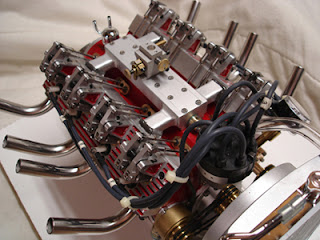
Dave Sage's "Howell V8"
I finally finished the V8 version of Jerry's V4.
I haven't run it yet. I thought I'd post some pictures before it scatters around the shop.
It's hard to believe it's been three years or so in construction. I hope it runs.
The intake manifold is a prototype since I'm not sure how many carburetors it will require. I can add more or move them around by simply making a new top plate for the manifold.
Weather permitting, I'll bring it to Cabin Fever in a couple of weeks.
Enjoy !
Dave Sage


----------------------------------
Really nice job. I'm working on the V4 and currently machining a set of intake and exhaust manifolds for it since I don't have the casting kit. I've finished the intake manifold and the exhaust manifolds are also nearly finished. I plan to be at Cabin Fever and hope to see you there.
Terry Mayhugh
---------------------------------
Yes Terry I saw your post and pictures of the intake manifold you made. Nice work, you must be very CNC savy. I know I had quite a time getting the height above the block for the water passage connection, the angle of the runners and their connection to the heads, and getting them to all come together at the same time.
The manifold I have is a temporary outfit. The top plate comes off so I can make a new one to accomodate more carbs. Below the plate is just a big cavity to act as a runner.
I'm pretty sure I'm going to need more than one carb but I started there. I made 6 carbs while I was set up to make them. Some for future projects I'm sure.
I really hope the weather holds so I can get to Cabin Fever (from Toronto). Please look me up. I'll be looking for all the V4's - hopefully you'll bring yours along regardless of it's state of completion.
Dave
---------------------------------
The V8 is running !
And Yes I think it's going to need at least one more carb. If you look at Sherlines Craftsmanship Museum - Howell V4 build page, at the very bottom, you'll see the pictures and a video of the V8 running. Thanks to them for that. It's a really good page to look at just to get an understanding of what is involved in building the V4.
Here's a direct link to the video
Still lots more work to do to get it to run better.
Sage
Subscribe to:
Posts (Atom)