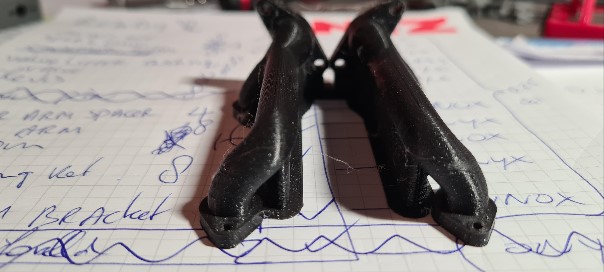
Finished my first model engine!
Attached are photos of my 4 in 1 vacuum engine. Runs great and learned an incredible amount in the process. Probably going for a Stirling next.


Finished my first model engine!
Attached are photos of my 4 in 1 vacuum engine. Runs great and learned an incredible amount in the process. Probably going for a Stirling next.

1) Add a .01uF capacitor (10nJ100) at I11-I14 right behind block B2 (pointed to by the longer red line in the photo). There is barely enough space and this must be installed before block B2. If B2 is already installed, try installing it on the bottom side of the PCB (but beware the "letter" coordinates are different on the bottom side of the PCB, B11-B14 to be exact)
2) Add a .1uF capacitor (.1J63) to block B1 positions 1 and 2 (pointed to by the shorter red line in the photo). See the original instructions of you are not sure of the location of the two positions.
As a side benefit, I have discovered that the 3PI-X will operate at 12 volts with the addition of these capacitors. I have not tested the longevity of the module at 12 volts, so proceed at your own risk! Overheating is much less likely if the auto-timeout jumper is enabled (attached), but regardless, check if any components are getting warm or hot every minute until you're confident it's running cool.
Since I developed the 3PI ignition module in 2024, I have sold 2 or 3 dozen kits and have not had any reports of any issues until I received the following e-mail from Justin Snyder on Jan 25, 2026. I have not had a chance to test his changes (but will soon) but I have no reason to doubt his results. See his email is below:
---------------------------------------------
Hello,
I purchased the 3PI-X ignition module awhile back. I had a few issues getting it working reliably. It really messed with me debugging my new hit and miss model engine. I went through several 555 ICs and a couple 2N4124 transistors.
I was about to email you for troubleshooting tips but after a lot of research and reading about similar circuits, I believe the issue was stray voltage created by the coil. Adding extra grounding was not enough. To fix the issue, I added the optional 0.01uF cap to pin 5 of the 555 chip as well as adding a 0.1uF bypass capacitor between pin 8 (VCC) of the 555 and ground. So far no more blown 555 chips and reliable performance. These should be part of the circuit as added protections.
I hope this helps others so they don't have to go through what I did to get it working reliably.
Thank you again. I built one. Next will be the rest of the engine.
A few photos are attached.
John
On Monday, October 7, 2024 at 09:01:57 AM EDT, John Laudano <john.laudano@att.net> wrote:
Thank you Allen.
the world misses guys like your dad.
John


Hello Allen
I just wanted to let you know that I finished my Farm Boy No. 1019 , this is the first engine I’ve ever built and I really enjoyed it. Your prints are excellent. I was a pattern maker for 30 years and it seems that there were always a few missing dimensions. Your prints were very complete !
I thought you might like to see some pictures. I haven’t painted it yet and maybe I won’t, having too much fun just watching it run!
I see in one of the photos of someone else’s engine that they built they had an oval Farm Boy plate made for the side of it. Any idea where it could possibly get something similar ?
Thanks Again
Jon


Hello Allen,
Just a note to let you know that my FarmBoy engine, Serial # 1033 is finished and running well. I downloaded the plans in March this year and worked on it steadily since then. I used the buzz coil ignition with spark saver option, a standard length Rexcel plug and a 4 AA battery pack. I did depart from the plans a bit to build it as a six bolt head instead of four, just to put my own mark on the model.
The plans are excellent but I can confirm there are two errors on sheet 3. As identified by Andrew Whales in his build series on YouTube, the horizontal spacing between the crankshaft and cam shaft is 1.031" for 48DP gears, not 1.026" shown on the drawing. The other error is that the 0.325" dimension for the cam mounting pad thickness on the Rearward View should be 0.355" as confirmed by the correct 0.105" (plus 0.25") dimension for the pad shown on the Bottom View.
The engine started and ran on the very first attempt, startling me completely! The only adjustments I made was experimenting with governor spring force, initially using a rubber band to get a feel for the right tension and then making the light spring shown in the attached video link which is a short clip of the fourth run. I've raised the speed slightly with the adjusting screw in the catch lever and finished the mounting bolts with nyloc nuts etc since that clip was filmed. The only things left are the crank bearing oil cups and deciding on a paint scheme or maybe leaving it natural.
Thanks again for the quality products,
Regards
Alan Gorlick
Qld, Australia

https://www.icloud.com/photos/#/icloudlinks/09eIMdROuPz9pF8GblRNJj0Og/0
It has come to my attention that there appears to be a dimensional error on page 5 of the Powerhouse plans. On "Frame Side View" (upper left), the dimension of .281 for the distance from the edge of the frame to the location of the push rod bracket holes, should be ~ .210 to .213 instead. If .281 is used, then the leftmost pushrod bracket located 2.156" away will be too close to the cam gear.
Many thanks to Jay Bolyard and his son Erik who caught this.
I'm very surprised that this has not been brought to my (or Dad's) attention until now as the plans have been around since 2001!
Regards,
Allen


Hi

Hello Allen
Thanks again for the drawings i have finished the engine. it was a great project to make here are some pictures of the farmboy #995.
kind regards.
mark journee from the netherlands


Hello Allen
First of all thank you very much for the plans! I'm almost in love with making the parts. I've made some progress since I have some free time at the moment. I make the farm boy a little bit different from the original but here are some pictures of the engine:


Hi Allen,
A "little" comparison with my previous Ford V8 flathead 1:3 model I made.
Your father's V4 is really tiny.
I am hoping that the Howell Vfour will end up looking just as nice. (Don't look at the engine stand yet, that was a fail to be rectified soon).
Take care.
Kees
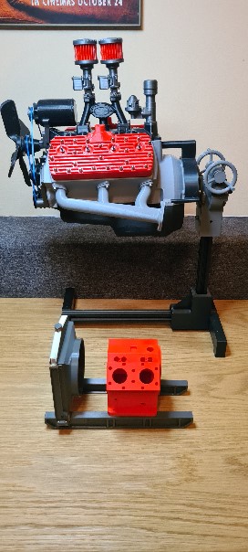


Kornelis Bijker from The Netherlands is building a 3D printed version of Dad's V4 engine. Here's his latest update:
----------------------------------------------------------------
"Hello Allen,
It is quite the trip I have to say. I think I have 95%+ of all the parts modeled by now, and started modifying the fits, fasteners and certain details for 3d printing.
Things like the con rods I cannot print in one piece, so I had to modify them to have a bearing cap, a very small bearing cap. The miniature bearings are 2.5 mm wide so the bolts holding them on will be just M1.4, the tiniest I have ever used.
Most of the original designs I try to keep, but some parts are simply to difficult to print like that.
The guts of the engine will have all working mechanics, like crank, pistons, cams and timing gears, lifters and moving pulleys.
But internals of pumps and ignition will not have moving mechanics. Simply too small and too detailed for FDM printing to work well. And in a plastic model without petrol combustion, I do not need cooling or oil anyway.
Still not sure where I will build in the electrical motor. If not inside the crank case I might have to "invent" some fictional starter motor. Maybe a bell-house with a large gear instead of the flywheel. Not decided yet.
But as of now the fasteners have been modified to metric, so have most of the bearings. They are easier to find here then the ANSI style and imperial bearings.
I also have started printing things, mostly as a test to help decide tolerances and such.
I was quite happy that the fan shroud printed as well as it did. Also happy how the radiator insert came out, you can actually see through it.
Some things still to do are the throttle linkages, and yes the distributor will advance as well. I also will attempt to connect the speed potentiometer with the throttle link so that the engine will respond to the throttle. The sound is another story."
------------------------------------------------------------------------------
The first 4 images are the 3D software renditions of the V4, and the last three are actual 3D printed radiator parts. Nice job Kees! Looking forward to seeing this to completion!