Photos of customer builds of Jerry Howell designed engines, Q&A's, and other items of interest
Wednesday, February 28, 2024
Friday, March 17, 2023
Kees Bijker's Flathead V8 vs Howell V4
Hi Allen,
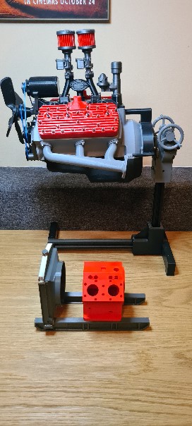
A "little" comparison with my previous Ford V8 flathead 1:3 model I made.
Your father's V4 is really tiny.
I am hoping that the Howell Vfour will end up looking just as nice. (Don't look at the engine stand yet, that was a fail to be rectified soon).
Take care.
Kees
Tuesday, March 14, 2023
Kees Bijker's 3D printed V4
Kornelis Bijker from The Netherlands is building a 3D printed version of Dad's V4 engine. Here's his latest update:
----------------------------------------------------------------
"Hello Allen,
It is quite the trip I have to say. I think I have 95%+ of all the parts modeled by now, and started modifying the fits, fasteners and certain details for 3d printing.
Things like the con rods I cannot print in one piece, so I had to modify them to have a bearing cap, a very small bearing cap. The miniature bearings are 2.5 mm wide so the bolts holding them on will be just M1.4, the tiniest I have ever used.
Most of the original designs I try to keep, but some parts are simply to difficult to print like that.
The guts of the engine will have all working mechanics, like crank, pistons, cams and timing gears, lifters and moving pulleys.
But internals of pumps and ignition will not have moving mechanics. Simply too small and too detailed for FDM printing to work well. And in a plastic model without petrol combustion, I do not need cooling or oil anyway.
Still not sure where I will build in the electrical motor. If not inside the crank case I might have to "invent" some fictional starter motor. Maybe a bell-house with a large gear instead of the flywheel. Not decided yet.
But as of now the fasteners have been modified to metric, so have most of the bearings. They are easier to find here then the ANSI style and imperial bearings.
I also have started printing things, mostly as a test to help decide tolerances and such.
I was quite happy that the fan shroud printed as well as it did. Also happy how the radiator insert came out, you can actually see through it.
Some things still to do are the throttle linkages, and yes the distributor will advance as well. I also will attempt to connect the speed potentiometer with the throttle link so that the engine will respond to the throttle. The sound is another story."
------------------------------------------------------------------------------
The first 4 images are the 3D software renditions of the V4, and the last three are actual 3D printed radiator parts. Nice job Kees! Looking forward to seeing this to completion!
Monday, October 10, 2016
Bob Cooke's V4 Update
Friday, December 19, 2014
V4 Water Pump Q&A w/Dave Sage
Re: magnetic drive water pump:
I have a question for those who have built the magnetic drive water pump.
Have you checked the operation of your water pump and confirmed it is moving water? Perhaps did you happen to check it off the engine.
I built the pump for my V8 version of the V4 several years ago and I'm pretty sure I saw it moving water - at least a few bubbles went by in my clear hose. Now I'm not so sure it's working - or ever worked properly.
I took it off the engine and cleaned it up and tested it off the engine and sure enough it doesn't pump. The magnetic coupling is not the issue the impeller is moving and you can tell when the magnets "cog" when they slip.
I recently needed another pump for a new engine so I built a slightly larger version with a direct drive shaft and made (what I think) is a better impeller. But still no pumping action.
I looked at pictures of some others that people have built and best I can tell they look like mine and appear to be what's in the drawings so I don't think I interpreted anything wrong. I'm not sure why it doesn't pump.
I'm very interested to know if there might be something wrong with the design although if Jerry made it probably worked. So it's probably something I've done wrong (twice).
Has anyone else made one of the pumps and actually confirmed operation.
Thanks
Sage
Thursday, November 20, 2014
Saturday, June 21, 2014
Bob Merva's Completed V4 (Serial# 002)
Thursday, January 9, 2014
Mic McAuliffe's V4 manifold drawings
------------------------------------------------------------
allen
attached drawings and photos
happy to help and explain or modify drawings to anyone, as mediocre
at drawings
working on a page by page beginners help of drawings if required
mic mcauliffe
Tuesday, November 8, 2011
More photos of Terry Mayhugh's V-Four
Friday, March 11, 2011
V-4 Distributor Miter Gear Source
REGARDS TURTLEHEAD
----------------------------------------
Here's what Jerry recommended to me via email when I asked him that question.
"The Stock Drive gears Part Number A 1B 4-Y48015 will work. I don't
know what the cost is.
wmberg.com has 72 pitch stainless gears that are more precision,
but they cost $65.00 plus $15.00 shipping. Part Number M72N-7S
I will probably get these a little later on when I make a 1-1/4" diameter
distributor for the V-Fout because they are far more precision than
the Small Parts or the SDP gears.
Regards,
Jerry Howell"
As above he suggests "Stock Drive Products" as a source of the original gears. You should be able to find your local distributor for them from their website.
The 72 pitch gears Jerry mentions are larger in diameter than the originals and are not a direct replacement.
Since I was making the V8, my distributor had to be designed larger in diameter (I chose 1-1/2") else the spark towers would be too close together so I re-designed the whole distributor with a larger tower diameter to accommodate them. Very expensive though, but they provide almost no backlash in the rotor which I guess should result in more accurate timing.
Sage
Friday, February 11, 2011
New Intake Design by Dave Sage
My new intake is made from bent stainless tubing - the same tubing and bender was used as the headers and the 90deg bends just fit. The whole assembly is silver soldered together. The carburetor is screwed onto a plate which is then screwed onto the stainless intake chamber. This will allow me to change carburetors if required by fabricating a new plate to suit the carb to be installed.
I can highly recommend separating the water funtion from the intake manifold function. This will also keep the intake charge cool instead of it being heated by the water.
Tuesday, January 11, 2011
Terry Mayhugh's fabricated exhaust manifolds
Sunday, January 2, 2011
Dave Sage's "Howell V8"
I haven't run it yet. I thought I'd post some pictures before it scatters around the shop.
It's hard to believe it's been three years or so in construction. I hope it runs.
The intake manifold is a prototype since I'm not sure how many carburetors it will require. I can add more or move them around by simply making a new top plate for the manifold.
Weather permitting, I'll bring it to Cabin Fever in a couple of weeks.
Enjoy !
Dave Sage