Showing posts with label V2. Show all posts

Tuesday, March 27, 2018

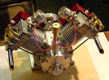
Cor Rademeyer's completed Howell V-Twin

Hello Alan

As promised, hereby a link to the video of my completed Howell Twin 4-stroke.

https://youtu.be/F44qsIr_AEA

Regards

Cor Rademeyer

------------------------------------------

Looks and runs great Cor.  Thanks for sharing!


Thursday, October 26, 2017

Hogan Half-Twin

I received this e-mail from Hogan Liechty back in Aug '17:
------------------------------------------------------------------

I am in the process of designing and building a single cylinder overhead cam 4 stroke model engine loosely based on the design concepts of Jerry's V-Twin.

I have not directly copied any of Jerrys designs but I have used them for inspiration.  Jerry's V Twin was the most difficult yet satisfying build I have completed.  Mine runs great.

Because it was so difficult to build the gear train and I wanted to try designing an overhead cam engine, I designed a single cylinder using Jerry's basic crankcase, cylinder, head, and flywheel concepts.  My final goal is to design a V-Twin OHC engine using the same concepts.

The obect of this e-mail is to give credit where credit is due. I have no desire to profit from my design work but would like to share it with the model making world.

I would be happy to give you a copy of my designs in PDF format and you can do with them what you want.  They are by no means ready to market on your web site since they are for my own shop use and are not fully detailed. If you want to complete them and make them market ready feel free to do so.  All I ask is aknowedgement  for the concept.

I am almost done with the build and will be trying to start my engine soon.  I have also shared part of my build on HMEM forum and have tried to give Jerry credit for the design concepts I have used.

I will attach a couple picture to show what I have done.

Please let me know if you want the drawings and will send them to you as soon as I have my engine running.

Thanks,
Hogan Liechty
---------------------------------------------------------------

Click on the photos below to enlarge.
Hogan sent me his drawings.  Click the link below to download for free or up to $5.00 donation.

Add to Cart

Great project.  Thanks for sharing, Hogan.


Monday, October 3, 2016

Steve Gould's V2

Here's an e-mail I received from Steve Gould on Oct 3, 2016:

--------------------------------------------------------

Hi Allen,

My Howell V2 engine is nearing completion, it’s a handsome looking engine and a bit more difficult to produce than my original assumption. There is still a number of steps to go before completion, but all the main parts are working fine and the cam gear train works very well. Here is a picture, it looks the part when polished!
Regards

Steve


Monday, May 11, 2015

V-Twin - Construction Comments by Ernie from south Florida

I started building the Howell V-Twin four months ago, although I have a long way to go, I would like to share some thoughts and ideas I picked up along the way. Disclosure: I am a self-taught machinist.

There are dozens of small parts on the Twin. None of which are difficult to make, with the exception of one, the gear case. It’s not for the faint at heart. Precision is a must. If you’re going to make the Twin, make the gear case. After you complete the case and cover, go on with the rest of the Twin. It’s downhill from there. Don’t get discouraged. it took me four tries to finally get the case right.  Pay particular attention to the depth of the gear pockets. Their depths are each measured from the top surface of the case, not the bottom of the 2.250 dia. x .270 deep cut out. The dimensions can be confusing so read the construction notes first. Note: The holes are first drilled on the “O” ring side, then turned over to bore the pockets.

Several gears will be needed; fortunately, you won’t have to make them. All, including the tail shaft and oil pump gears, can be purchased very inexpensively on eBay; however, they will require some simple modifications. The Howell drawings specify 14 ½ degree pressure angle. The PA of the gears I purchased was not specified, but they seem to work perfectly so far.

Before drilling the holes in the gear case, test drill the holes in a flat plate. Put the gears in place on the plate to verify the dimensions to assure smooth rotation. You may have to make minor adjustments to achieve minimal backlash. 

To make life easier I used a 1” ID DOM Steel Round Tube for a cylinder liner (available on line). The tube required modification of the cylinder as designed but it resulted in a perfectly round, and non-tapered inside diameter. No lapping is needed as the inside is perfectly polished. In addition, I’m going to try to use Viton "O" rings instead of cast iron rings. More on that latter.

I intend to add more as I proceeded, so stay tuned. And please, feel free to email me [ernie7@bellsouth.net] with any questions.

-------------------------------------------------------

A minor point concerning the oil pump and that's the gear offset from the center. There is no indication on how that gear is held in place. Just press a .125 dia. x .25 post into the center and place the gear over it. The gear will rotate around the post.

LOCKTITE 640 is specified in several places in the construction notes. DO NOT substitute another product. This stuff is incredibly strong up to 400 degrees. A small tube, although not cheap, will last a long time.

------------------------------------------------------
V-Twin – Pistons & Rings

On virtually every engine I built in the past, I had problems with compression. However, that problem is no more since I started to use DOM tubing as the cylinder liner. For the V-Twin, I am using 1” inside diameter DOM tube (from On Line Metals). As close as I can measure, the ID is spot on, 1.000" with no taper. The inside wall is polished smooth as glass.   Following is how I make the piston, cylinder and rings:
- Make the aluminum cylinder body first but with a 1.190” bore.
- Start with a 2” length of 1” DOM and turn the OD to 1.188” for a light press into the cylinder body, and then cut it off to length. Press it into the aluminum body.
- Make the piston blank by turning a 4” long piece of 1” diameter cast iron (which is always oversize) just enough so it is a tight sliding fit into your aluminum cylinder body. 
- Polish the piston to achieve a sliding fit into the cylinder. 
- Bore an .910” diameter hole ¾” deep in one end of the piston blank, actually the ID of the rings.
- Part off six rings from the piston blank (I usually cut off a few extra) each about .045” wide. 
- Now, cut the ring grooves as specified on the drawing and complete the two pistons.
- Using fixture A, sand (150 grit) the rings just enough to fit the width of the piston grooves.
- Using a diagonal cutter cut the rings forming the ring gap.
- Using a very fine file, lightly file the two ends of the gap. 
- Place the ring on fixture B.
- With a torch, heat the ring opposite the gap until it turns red for about 20 seconds.
- Remove the ring (let it cool). The gap will remain open but will  close with a little pressure then spring open when pressure is removed. 
- Now it’s a matter of putting the rings on the piston and inserting the piston/ring assembly into the cylinder. That may take a little effort.

You’re done! It took me about five hours. Hope this helps. Note: Email me for a sketch of fixture A&B.

-------------------------------------------------

I found machining the V-Twin carbonator quite challenging and one of the more difficult parts to make next to the gear case. So much that it took me three tries to get it right. In my opinion, the original drawing is just too confusing and that lead to the errors in machining the part. As a result I redrew the carbonator body using conventional drawing and dimensioning practices. If you would like the drawing send me an SASE and I will gladly send it to you, but ONLY if you purchased the V-Twin drawing set from Howell. Email me --- ernie7@bellsouth.net


Tuesday, March 3, 2015

V2 fan hub assembly explained

Here's an e-mail thread I thought would be a good topic to share with others:

---------------------------------------

Hi Allen,

Last time I emailed you, I was 80% complete in a few months, I’m getting a little closer now.

I’m working on the fan, Sheet #35. Because there are no assembly drawings on many of the subassemblies, it makes things interesting, like a puzzle. The fan hub takes a .156 x .312 flanged support bearing for the Fan Shaft. But where does the other bearing go. (a shaft needs two support bearings). I assume it goes in the Fan Belt pulley. But in you kit of bearings there is no bearing that size.

As always thank for your help.

Ernie

From South Florida: Weather report for today - 81 degrees

---------------------------------------------

Hello Ernie,

Hey - no fair bragging about your weather!

After some study and speaking as an amateur, here's what it looks like to me:

1. Insert a .156 ID x .312 OD x .125 flanged bearing, flanged side out, all the way onto the Fan Shaft.
2. Insert the Fan Hub into onto the Fan Shaft, narrow end attached to the bearing from step 1.
3. Insert the second .156 ID x .312 x .125 flanged bearing on the Fan Shaft, flanged side out.
4. Insert the Fan Belt Pulley onto the narrow end of the Fan Hub.
5. Attach the Fan Mounting Bracket on the remaining exposed end of the Fan Shaft.

See if that makes sense to you.

Allen

---------------------------------------------

Allen

That cleared it up.  In summary there is a ball bearing inserted on each end of the Fan Hub. But, why is there a .500 dia x .190 dp cut out in the Fan Belt pulley. I think it would have made more sense to put the other ball bearing in the Fan Belt Pulley. 

One more thing, the gears. Cutting gears is expensive due to the cost of the gear cutters and a rotary table. The gears can be purchased from SDP or other gear houses, expensive. However, I purchased then on eBay for about $3.00/gear. Only slight modification is needed. If you would like more info just ask me. You may want to pass it off to others.

I certainly appreciate the help, thank you again.

Ernie

--------------------------------------

Yeah, I wondered about that deep cut on the Fan Belt Pully.  I can only guess that Dad did not think it needed all of that bearing surface contact, and also makes it easier to disassemble should the need arise.  He knew he would have to disassemble the engine after he built it to draw up the plans (contrary to typical product development, Dad built his engines first, then developed the plans after!)

Send some of that sunshine and warm air up here.  We could use it!

Allen

Tuesday, December 16, 2014

V2 crankshaft and tailshaft bearing placement confusion resolved

Q&A e-mails with Ernie (Q) from South Florida and me (A):

--------------------------------------------------------------

Q: Sheet #22, Crankshaft – The bearing diameter portions of the shaft as noted on the drawing are .500” & .437”.  However, the bearing used on the shaft have inside diameters of .500 which is OK, but the other is (supplied by you) 12mm. However, 12mm = .472”, therefore, the .437” shown on the drawing must be wrong; it should be .472” or 12mm.  The bearing supplied is 12mm ID x 21mm OD x 5mm thick.

A: The crankshaft in the V2 is not like a traditional one-piece crankshaft where you have two ends with the connecting rod throw in the middle.   Basically, this shaft has just ONE end.  On the other side of the crankdisk is the tailshaft.  Both crankshaft bearings are mounted to the crankshaft, but on the SAME side of the crankdisk.  See the crankshaft housing on page 13.  Both crankshaft bearings fit in the housing, and the crankshaft slides into BOTH bearings.

The other side of the crankdisk is the tailshaft (Pg 10), supported by two bearings, with the inner tailshaft receiving the 12mm x 21mm x 5mm bearing, and the outer tailshaft will receive the .250 ID x .500 OD x .187 bearing.

Q: Look on page #18, the figure in the upper left. Note the tailshaft (it is .375” dia.) The ball bearing is 12mm ID x 21mm OD x 5mm thick.  12mm is .472”.  How does a .472 dia. bearing fit a .375 dia. shaft?

A: Both crankshaft bearings are .500 ID, and they BOTH slide onto the .500 diameter section of the crankshaft as illustrated at the top of page 22.

The 12mm ID x 21mm OD by 5mm bearing is NOT mounted on the tailshaft, but rather, it is mounted on the Tailshaft Crankdisk, bottom right on Pg 22 (thus the .472), and the tailshaft is inserted into the crankdisk (thus the .375 ream).

Monday, March 18, 2013

David Lavoie's V2

Got this e-mail from David on March 18, 2013:

--------------------------------------------

Hi Allen,
I got the Sensor squared away finally, The ground was at the base of the engine and it was not liking it there, I have my engine all anodized and it is cool looking, I have it running and here is a link to my engine site with pictures.


Thanks David Lavoie


Sunday, September 11, 2011

Dana Hall's V-Twin

Here's an e-mail I received from Dana on Sep 11, 2011.  He did a superb job indeed!

--------------------------------------------------------------------------------

Hi Allen...
Dana Hall here from central Florida...

At the start of this year I purchased Jerry's "V Twin" plans, and just
finished building the engine today... Just about 8 months for me to make this...
Enclosed are 3 images of the engine I thought you might like to see...

Looks like the "Bill" engine is next...


Friday, October 29, 2010

Monday, June 30, 2003

Jerry's Original "Howell V-Twin" (V2)

"This is a V-Twin engine that is machined entirely from bar stock. It has no prototype as it is entirely my own design. Being a single crank pin 90 degree engine, it is extremely smooth and vibration free. V type engines other than 90 degree can not be balanced except with special balancer shafts, etc. that you wouldn't want! Witness the vibrating 45 degree motorcycle engines...... The engine is a long stroke, moderate speed design which provides plenty of torque. A robust cooling system allows the engine to run indefinitly with a load and never overheat." - Jerry Howell

Revisions to the plans are posted at:
http://www.jerry-howell.com/V2-Revisions.html