Photos of customer builds of Jerry Howell designed engines, Q&A's, and other items of interest
Sunday, January 1, 2023
Saturday, December 3, 2022
Pat Janson's freelance Hit n Miss
It’s freelance and completely done with bar stock except for the flywheels, crankshaft and connecting rod. The flywheels are cast iron caster wheels found on EBAY, machined down to be round and concentric. The crank and rod were salvaged from an old broken sewing machine. When I saw the parts in the sewing machine I immediately decided that they would make a great engine. That was 20 years ago.
I’m retired now and finally started building it. I’m so close to starting for the first time, but am having problems with the carburetor. I’ve made 3 so far and still cant make it work. I’ll get it sooner or later.
I got the TIM 6 ignition from you and assembled that without problems .. I seem to have good spark.
I thought you’d like to see my project.
Thanks,
Pat Janson
Old Orchard Beach, Maine
Saturday, April 9, 2022
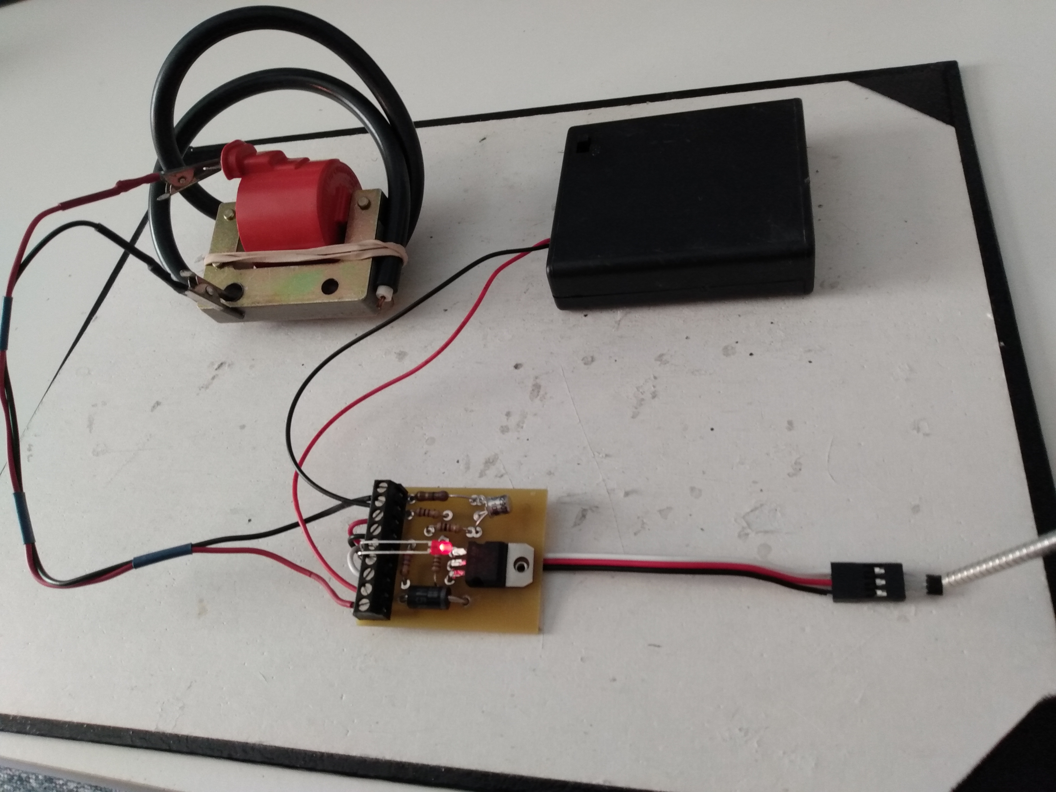
TIM6 Ignition Module / ATV Coil Bench Test Procedures
Once you get it working on the bench, proceed by installing just ONE component at a time on the engine, and re-test. If it still works, install the next component and re-test. Repeat until the entire system is installed. If it quits working after you installed a particular component, then you know you have a connection problem with that component.
See the photos below for how I bench test the TIM6 with the ATV coil.
- The tab on the coil connects to "Coil +" and the coil frame is connected to "Coil -" on the TIM6 module.
- Cut the end of the coil's spark plug cable so that about 1/8" of the copper wire is exposed. Secure the spark plug wire to the coil frame so that the exposed wire is 1/16" to 1/8" from the coil frame. No more, no less or you can damage the coil. The spark will jump here.
- Connect your 6v battery to "6 volt+" and "6 volt -" on the module.
- Using a bent paper clip, quickly touch and release the "points" terminals on the connection block several times. This simulates a "points" system. Each time you make a connection you should see the LED light up, and when you release a spark will jump across the gap of the spark plug wire and the coil frame.
- Switch off power, or disconnect "6 volt +" on the module
- Hook up the Hall sensor to the switch block following the TIM6 Instructions, or as shown in the photo below using our Hall wire.
- Reconnect power.
- Spark Plug
- Points or Hall/Magnet
- Make sure the Hall sensor install, and it's wires, are well insulated from the engine frame. Some of our instructions recommend you also ground the module (from the "Gnd" on the board terminal block) to the engine frame. This is to provide a path for the coil's high voltage to ground in case the Hall sensor or wiring is too close to the engine. If you're getting good spark after installing the spark plug, hold off on this step. However, if your have a problem with Hall sensors blowing out, try this ground.
- TIM6 module
- Battery
Friday, April 8, 2022
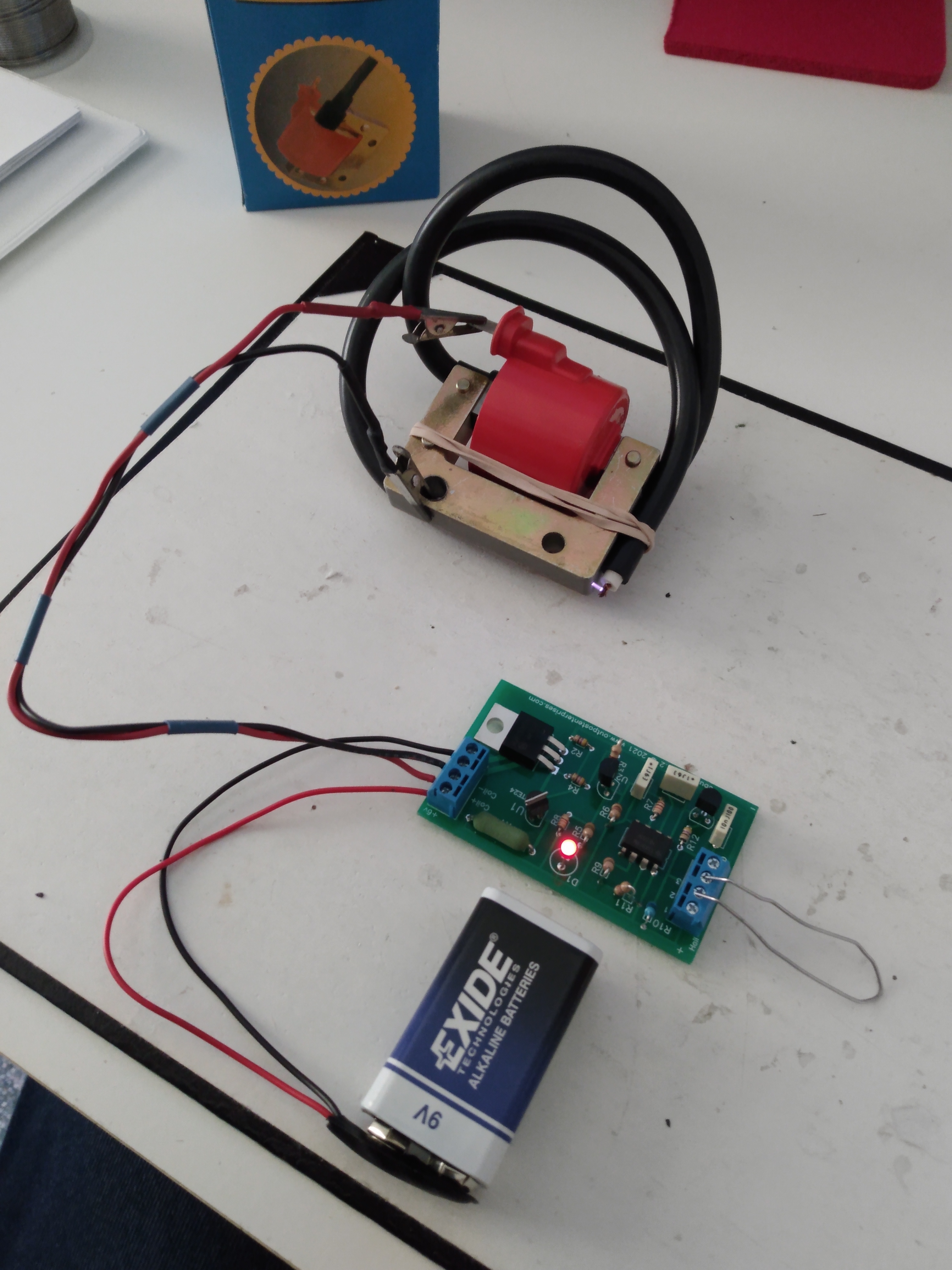
BuzzCoil Ignition Module and ATV Coil Bench Testing
Once you get it working on the bench, proceed by installing just ONE component at a time on the engine, and re-test. If it still works, install the next component and re-test. Repeat until the entire system is installed. If it quits working after you installed a particular component, then you know you have a connection problem with that component.
See the photos below for how I bench test the BuzzCoil with the ATV coil.
- The tab on the coil connects to "Coil +" and the coil frame is connected to "Coil -" on the BuzzCoil module.
- Cut the end of the coil's spark plug cable so that about 1/8" of the copper wire is exposed. Secure the spark plug wire to the coil frame so that the exposed wire is 1/16" to 1/8" from the coil frame. No more, no less or you can damage the coil. The spark will jump here.
- Connect your battery (I use a 9v smoke alarm battery) to "Batt +" and "Batt-" on the module.
- Using a bent paper clip, quickly touch and release positions 2 and 3 on the switch connection block. This simulates a "points" system. Each time you make a connection you should see the LED light up and a "shower of sparks" will jump across the gap of the spark plug wire and the coil frame.
- Disconnect Batt +.
- Hook up the Hall sensor directly to the switch block following the BuzzCoil wiring diagram PDF, or alternatively use steps 3-4:
- With the Hall's beveled edge facing down, insert the Hall Sensor into the switch terminal block positions 1,2 and 3.
- With your needle nose pliers, grasp the Hall legs in the middle and bend the head up.
- Reconnect Batt +.
- Spark Plug
- Points or Hall/Magnet
- Make sure the Hall sensor install, and it's wires, are well insulated from the engine frame. Some of our instructions recommend you also ground the module (from the "Gnd" on the board terminal block) to the engine frame. This is to provide a path for the coil's high voltage to ground in case the Hall sensor or wiring is too close to the engine. If you're getting good spark after installing the spark plug, hold off on this step. However, if your have a problem with Hall sensors blowing out, try this ground.
- BuzzCoil module
- Battery
Thursday, March 3, 2022
Francisco Herranz's Powerhouse
From an email I received on Feb 14th:
Monday, December 27, 2021
Friday, July 2, 2021
Steven Green's Super Fan
Got this email from Steven on July 1, 2021:
---------------------------------------------------
Allen,
Several years ago I built a Stirling engine from (cheap) plans bought at a show. The engine didn’t run very well so I began to search the internet to diagnose the problem. That’s when I came across an article Jerry Howell Models had on-line explaining some of the reasons some engines don’t run very well. A very good article.
I ordered the plans and materials kit for the Super Stirling Fan and it set on the shelf for more years than I care to admit. Last Fall, after retiring, I decided to build the fan, but not just one fan, I built one for each of our children and one for us, 5 total. All the fans run great and the kids love them. I have ran mine at engine shows for as long as 6 hours at a time and it gets a lot of attention. One gentleman, while watching the fan run was explaining to his friend that the engines will run for a short time then get too hot to continue running. This gave me the opportunity to tell him my story of the first engine that I had built and that this fan had been running continuous for about 4 hours. I gave him your website information.
Thanks for keeping the business going to provide us gearheads with very well designed “stuff” to build.
Steven Green
My Wife let me decorate the mantle last Christmas.
--------------------------------------------
Steven, I love hearing stories like this. Thanks for the email!